The installation files for the Vivado Design Edition can be downloaded from the Xilinx web site.
http://www.xilinx.com/support/download.html
There are a couple of things to keep in mind when planning the installation:
- Install Vivado version 2015.2. Some of the Arty demo design build scripts will check the Vivado version and only accept 2015.2.
- Install the Vivado tool to the folder C:\Xilinx. Many demo scripts expect that the Vivado has been installed to the default location.
If you want to keep your applications on a separate windows partition you can create a junction with the mklink command. E.g. if you want to place the tool to D:\Apps\Xilinx but install and access it via C:\Xilinx:
C:\> mkdir D:\Apps\Xilinx

C:\> mklink /j C:\Xilinx D:\Apps\Xilinx
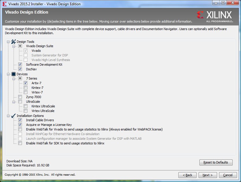
When selecting the installation options just select the Artix-7 device. Also select the Software Development Kit.
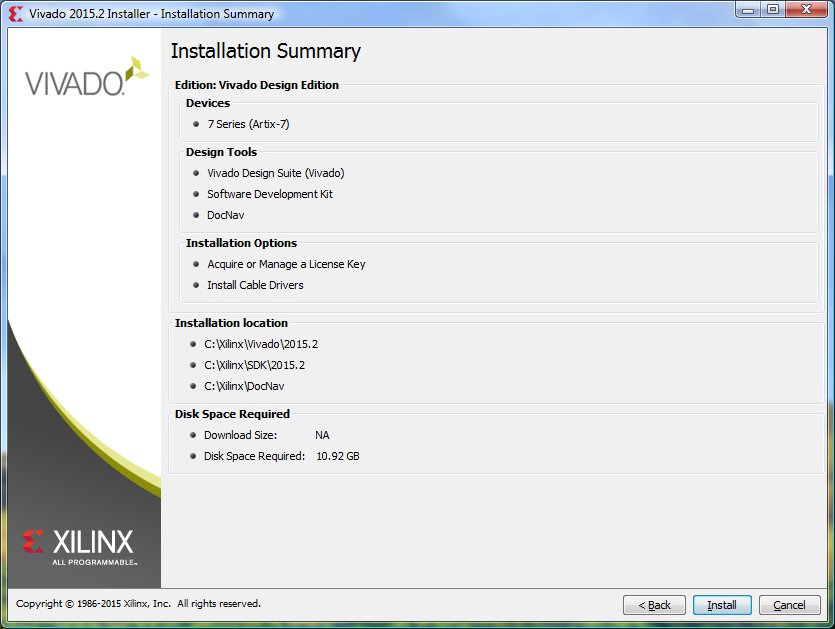
Here is my summary page.
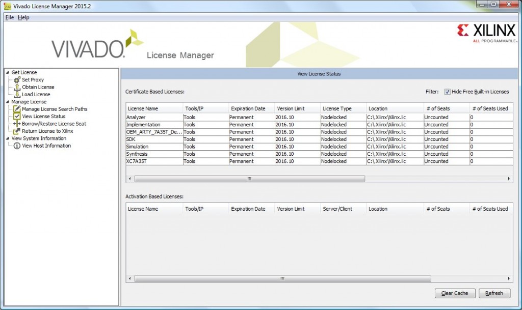
The license can be obtained with the voucher that came with the Arty kit. It will grant you one node locked license for using the Vivado Design Edition (just Artix-7 device support will be enabled by the license). When the license has been activated you can download the license file and install it with the Vivado license manager.
The license has a version limit of 2016.10. That means that we can have tool updates for one year.
The next step is to install the board definition file for the Arty board. You can download the the board package from the Digilent site:
https://reference.digilentinc.com/_media/vivado:board_files_09252015.zip
And then extract the arty folder and put it into the Vivado board repository in C:\Xilinx\Vivado\2015.2\data\boards\board_files.
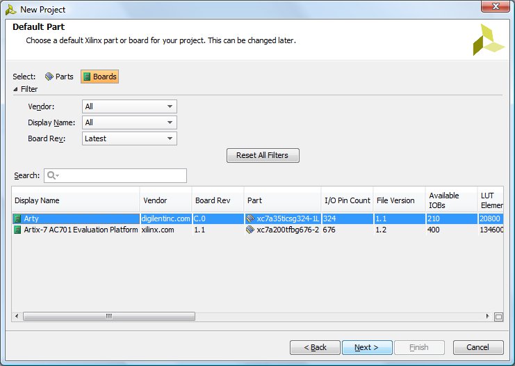
Now, when you run vivado and create a new project you can select the Arty board during the project setup.
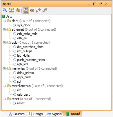
And the board components will become available in the project window.
The board definition is stored into the file board.xml under the board_files/arty/C.0 folder. The file basically describes the Arty board components and connections. There is also another file called part0_pins.xml that defines the FPGA pins (i.e. the LOC constraints) for each of the component interfaces.
Here is a local copy of the board definition file in case the digilent link stops working.
